Wattstopper Occupancy Sensor Wiring Diagram

Wattstopper How To Wire A Dt 305 Dual Technology Ceiling Sensor Youtube

Diagram Watt Stopper Occupancy Sensor Wiring Diagram Full Version Hd Quality Wiring Diagram Cardiagram Dn Mag Fr
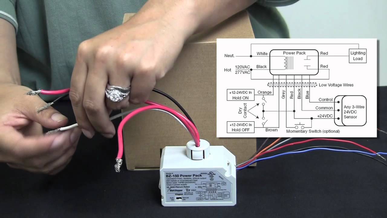
Wattstopper How To Wiring A Bz 150 Universal Voltage Power Pack Youtube
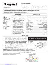
Legrand Wattstopper Pw 311 Installation Instructions Manual Pdf Download Manualslib
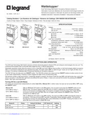
Wattstopper Dw 100 Installation Instructions Manual Pdf Download Manualslib

Wattstopper How To Video Dt 300 Occupancy Sensor Youtube
Assortment of ceiling mount occupancy sensor wiring diagram.
Wattstopper occupancy sensor wiring diagram.
Watt Stopper Help Electrician Talk

Pin Di Wiring

Ax 8163 Watt Stopper Wiring Diagrams Also Motion Sensor Light Wiring Diagram Wiring Diagram
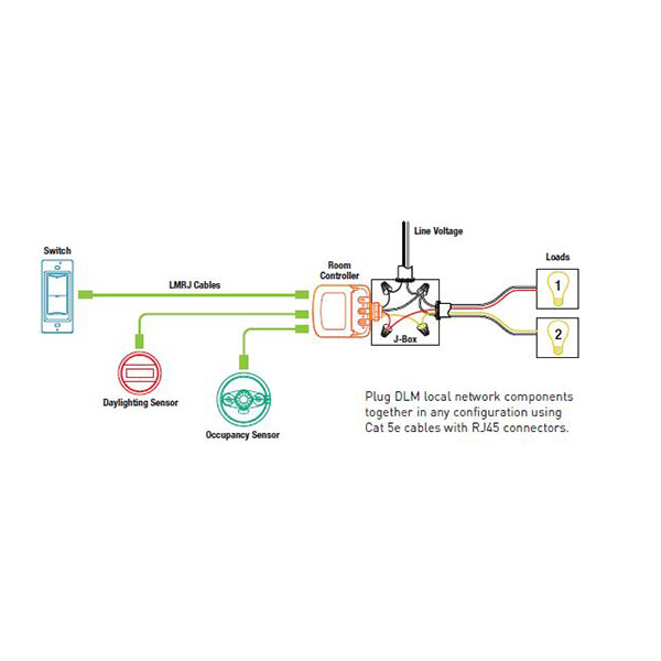
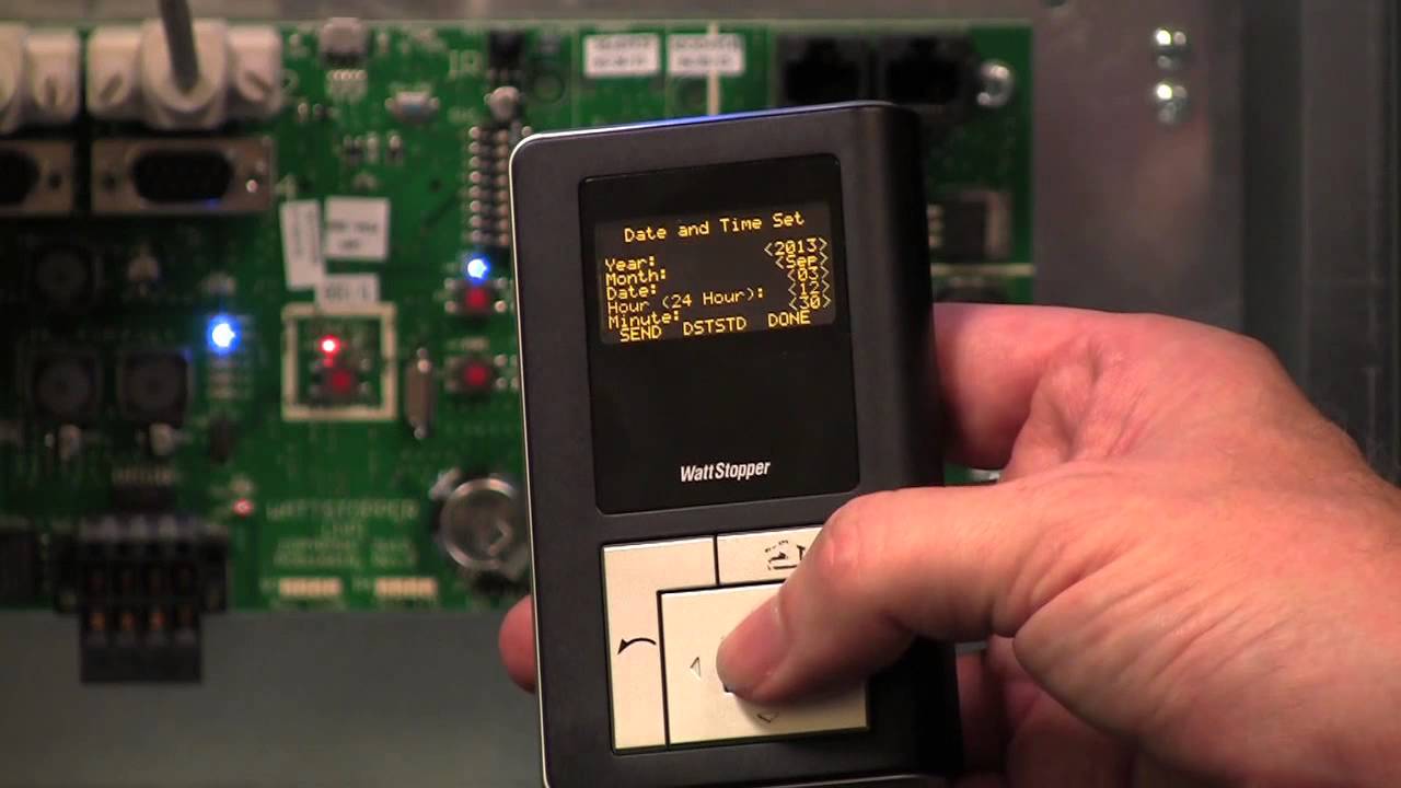
Lmrc 100 Series Digital Switching Room Controller Literite Controls
Source : pinterest.com
